Crane configuration
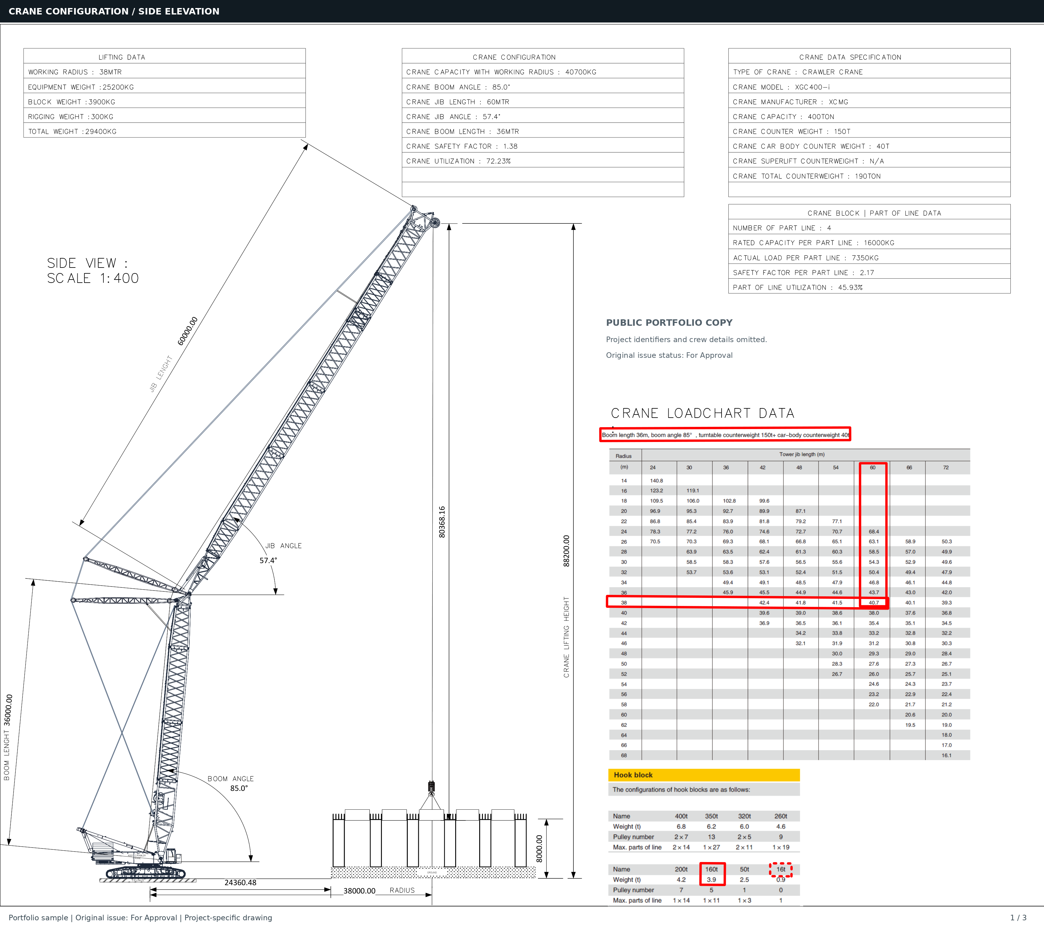
Side elevation, boom and jib arrangement, working radius, load information and the selected load-chart excerpt.

DRAWING PORTFOLIO / 01
Precast lifting plan · 38m working radius
Explore the crane configuration, site arrangement and rigging drawings in a supplied lifting-plan example.
ACTUAL SUPPLIED DRAWING / PORTFOLIO SAMPLE
THE DRAWING AT A GLANCE
Portfolio sample · Original issue: For Approval
Drawing & lifting-plan documentation
Abdul Salam Zulmajdi
Figures as shown in the supplied plan. Total suspended mass includes the hook block and rigging. The 400t figure identifies the crane class; capacity varies with configuration.
THREE SHEETS / ONE EXAMPLE
Choose a sheet to explore the drawing.
Zoom in to inspect the details.
Drag to pan when zoomed. Use the arrow keys to scroll the focused sheet.
Portfolio presentation of a project-specific drawing issued for approval. Technical information is reproduced from the supplied plan.
DRAWING & DOCUMENTATION
A look at the information brought together in this example.
Side elevation, boom and jib arrangement, working radius, load information and the selected load-chart excerpt.
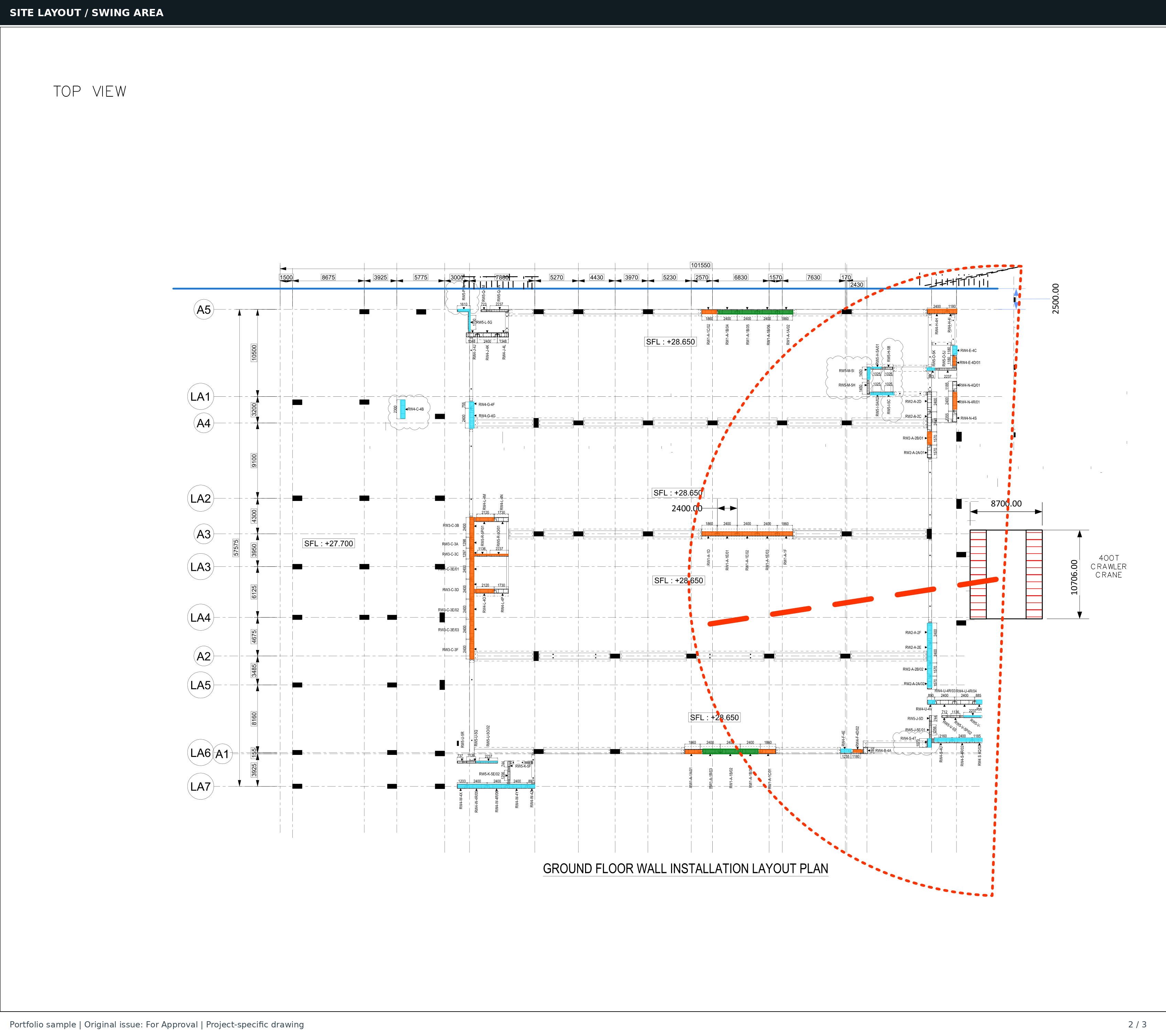
A top-view drawing connecting crane position and the depicted swing envelope to the building layout.
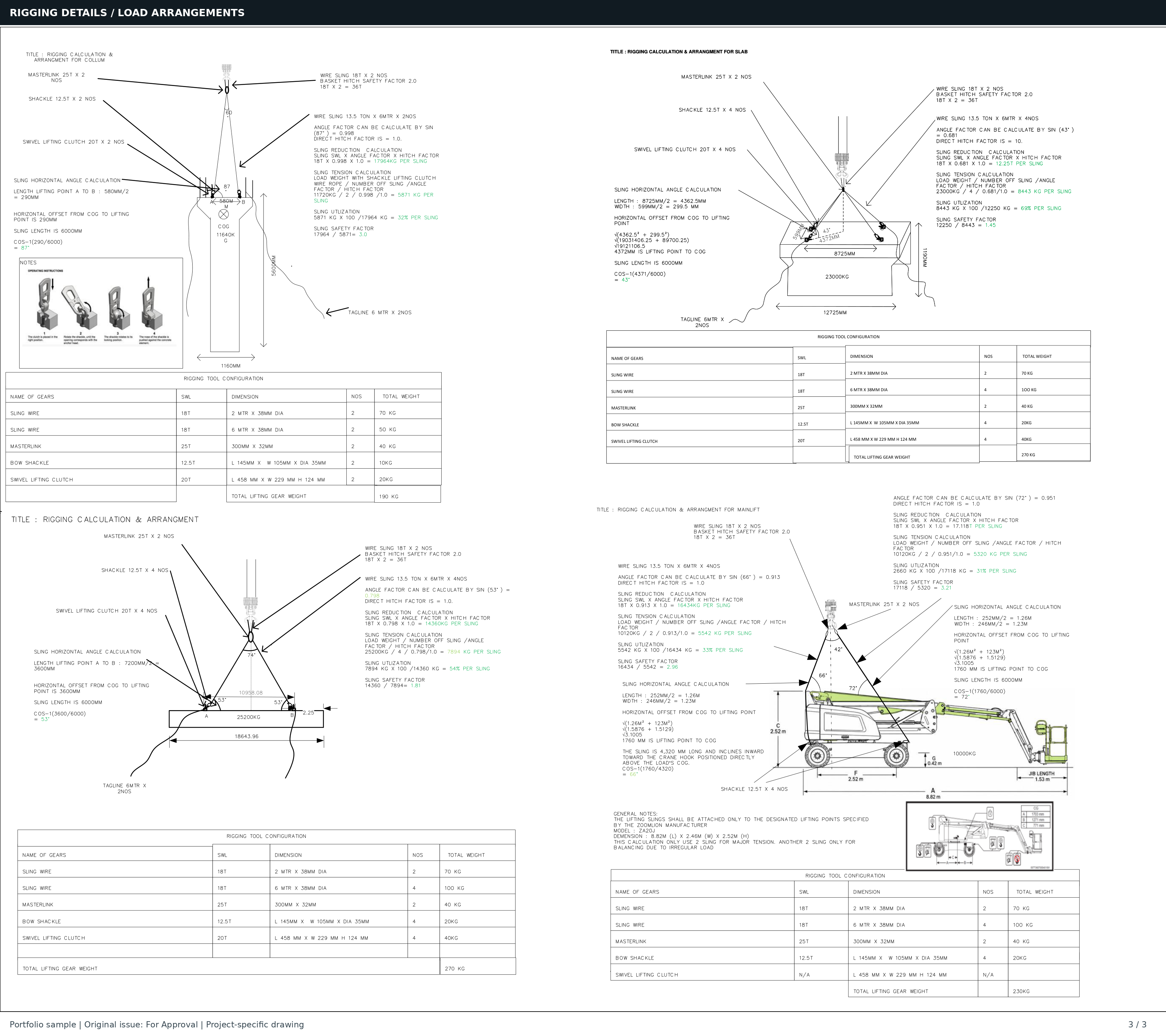
Supplied column, slab, beam and manlift arrangements with sling geometry, component details and lifting-gear schedules.
YOUR NEXT PROJECT
Share the load, site location, crane details and timing. Let’s discuss the scope of support.